

| Home | S-100 Boards | History | New Boards | Software | Boards For Sale |
| Forum | Other Web Sites | Quiz | Index |
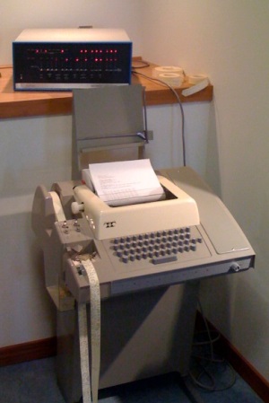
| The Altair and other early S-100 computers were envisioned as being connected to a Teletype terminal for data input and output. A typical setup was as shown here in this picture. However it was not long until people started to look around for a smaller, simpler and quieter mode of data entry and display. Don Lancaster's pivotal book "TV Typewriter Cookbook" was instrumental in helping people to put together their own computer CRT terminal using simple common 7400 TTL chips. | ||
 |
Two modes of S100 video display were used. One utilized part of the CPU's
64K memory address space to display text or graphics on a screen. The other
simply send ASCII characters to and external CRT terminal like the Lancaster
terminal mentioned above or to an S100 board that behaved like an external
CRT terminal, that is, it sent video data to an external CRT monitor. The first of the "in memory" S-100 boards was the Cromemco's TV Dazzler. However this board was best suited for graphics rather than text. Processor Technologies VDM board or the Solid State Music VDB-1 video boards were very popular early memory mapped video boards. They allowed decent readable text to be displayed on a CRT monitor. However the text was limited to 64 characters per line, but they were fast -- even for a 2MHz 8080. Some of the early video games were developed on these boards. The Sargon chess game with graphics was an early apex of this era. All this rapidly changed with the introduction of dedicated LSI CRT controller chips. These specialized microprocessors put on one chip the ability to display text on a CRT monitor utilizing just a few support chips. This lead to a number of interesting and popular "IO mapped" CRT display boards. These dominated the S-100 video display board systems in the end. An excellent example of a board like this was the SD Systems 8024 Video Board. These CRT controller chips are well described in a book by Gerry Kane titled "CRT Controller Handbook". There were (and still are) four popular CRT controller chips from that era. Let's look at each briefly:- |
|
|
The National
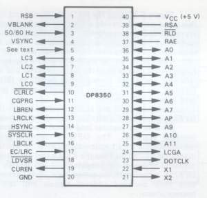
DP8350 The DP8350 CRT controller series was one of the later CRT controllers to be introduced and provided some functions not available on any of the earlier devices. Nonetheless, its operation was quite straightforward. One reason for its relative simplicity of operation was that some of the functions that were user-programmable in other CRT controllers were mask-programmable in the DP8350s. Mask-programming of certain functions made a great deal of sense because, while many functions need to be custom tailored to a particular design, they do not need to be altered once they have been established. The disadvantage of mask-programmable functions is, of course, that you must be a high-volume user of a particular programmed version of the DP8350 in order to justify the cost involved. If you needed only a few devices and one of the standard pre-programmed versions cannot be used, you would not choose the 8350. That said, the DP8350 series came in three standard ROM versions. These were:- DP8350 80 characters/row, 24 rows, 7x10 field DP8352 32 characters/row. 16 rows, 9x12 field DP8353 80 characters/row, 25 rows, 9x12 field |
 |
|
The
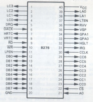
Intel 8275 The 8275 CRT controller was an interesting contrast to the DP8350. The designers of this chip had taken completely different approach to implementing the controller function. While both the DP8350 and 8275 devices allow you to specify many options, such as character size and timing chain parameters, the 8275 options are specified under program control instead of being mask-programmed as in the DP8350. The unique feature of the 8275 CRT controller was the inclusion of two 80-character buffers within the device. The presence of these data buffers and the microprocessor interface logic provided by the 8275 imply, and in fact demand, a very specific system configuration — one that is quite different from that which would be used with the DP8350. |
 |
|
|
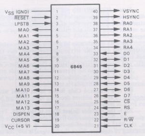
The Motorola 6845 The 6845 CRT controller was somewhere between the DP8350 device and the 8275 device in its functional organization and capabilities. It was similar to the DP8350 in the way that it was positioned functionally within a system; it coordinates the flow of data from screen memory to character generator logic and thence onto the CRT monitor, but data did not actually pass through the 6845 as was the case with the 8275 device. However, the 6845 was a fully programmable device, like the 8275, instead of being mask-programmable like the DP8350. The 6845 provided screen memory addressing logic but no memory contention logic. The light pen logic, cursor logic, and scan line counters provided by the 6845 were similar to those of the 8275, although the scrolling and cursor logic was more limited in the 6845. Similarly, the blanking logic provided by the 6845 was minimal, although adequate, and did not provide as many options as the 8275. No dot timing logic was provided on-chip, but HSYNC/VSYNC generation logic was present on the 6845. The 6845 provided a full complement of programmable registers, there were however no status or control registers or signals provided by the 6845 to simplify the microprocessor interface. The 6845's real claim to fame however was that it was adopted by IBM for the initial IBM-PC's video board. This lead to its wide use and software development and later to further CRT/video chips along the same lines. |
 |
|
|
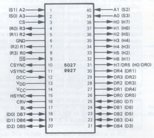
The SMC Microsystems 5027 The 5027 CRT controller was one of the first of the LSI controller devices introduced. The functions provided by the 5027 may appear to be somewhat more elementary than those available with other above devices. Nonetheless, the 5027 still provided several interesting functions not available on any of the above devices. |
 |
|
|
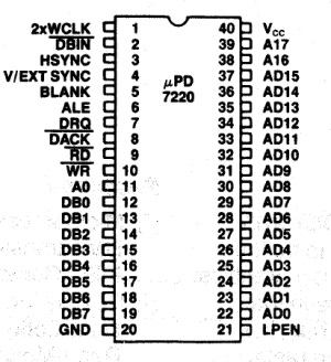
The NEC 7220 The 7220 video controller, (which came out in the early 80's), brought video display graphics to a new level. It was the NVIDEA chip of its day. There were two in NEC's personal computer and it was incorporated into a number of other high end desktop computers such as HP's, DEC and Epson. The 7220 "Graphics Display Controller" -- as NEC called it, was an intelligent microprocessor peripheral designed to be the heart of a high performance raster-scan computer graphics and character display system. Positioned between the video display memory and the microprocessor bus, the 7220 performed the tasks needed to generate the raster display and manage the display memory. Processor software overhead was minimized by the 7220's sophisticated instruction set, graphics figure drawing, and DMA transfer capabilities. The display memory supported by the 7220 could be configured in any number of formats and sizes up to 256K 16-bit words. The display could be zoomed and panned, while partitioned screen areas could be independently scrolled. With its light pen input and multiple controller capability, the 7220 was ideal for advanced computer graphics applications. |
 |
|
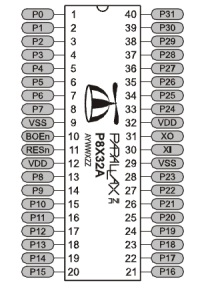
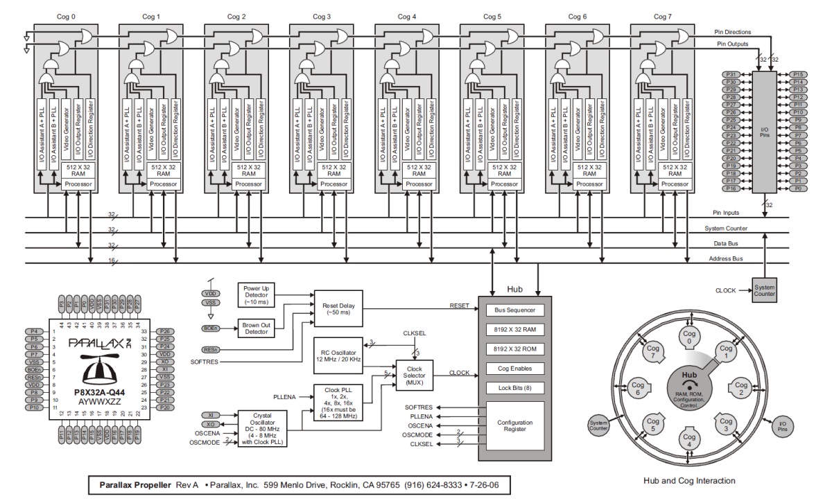
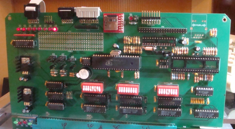
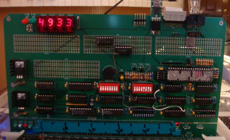
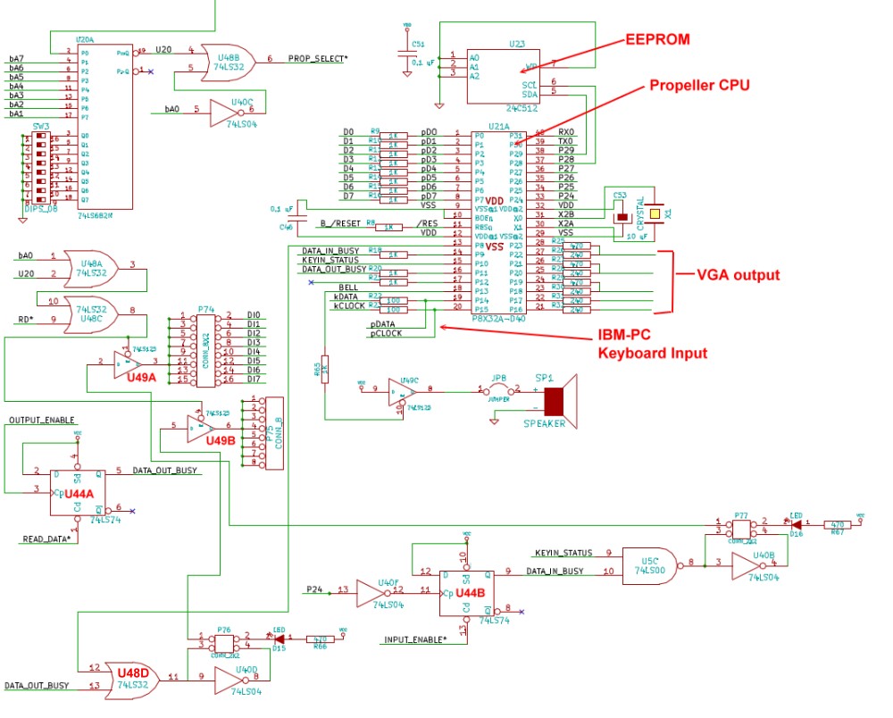
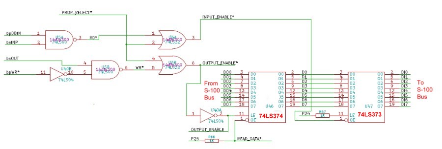
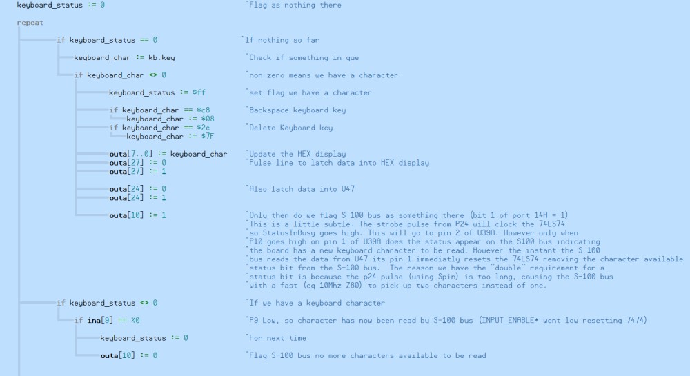
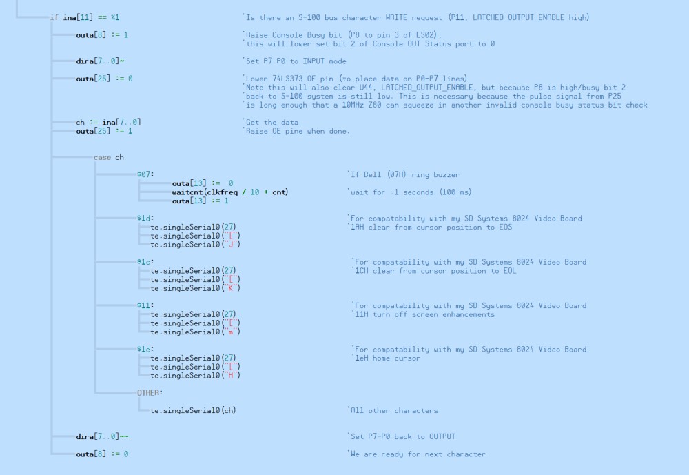
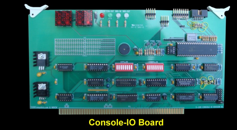
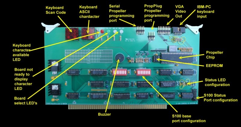
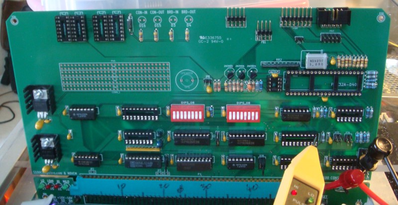
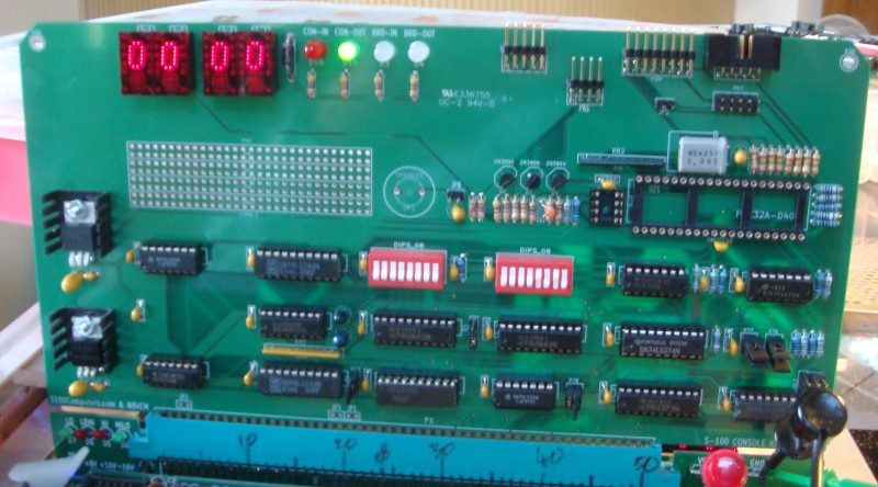
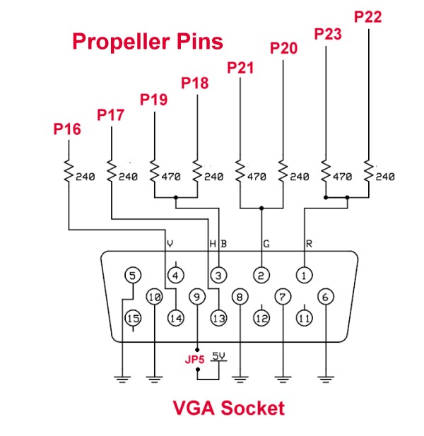
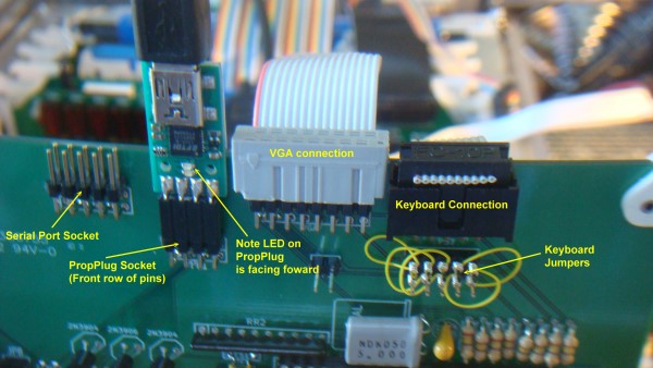
The Propeller P8X32 The Propeller P8X32 chip is a multi-core microcontroller. It has 8 cores, called "Cogs", 32k of shared RAM, 32k of ROM, and 32 I/O pins. The Cogs each have their own local memory, and share access to the 32k Hub memory. They also share access to the 32 I/O pins. They, also, each have their own pair of user configurable counters with PLLs and a Video Generator that aids in driving either NTSC/PAL or VGA video outputs. There are two types of RAM associated with this chip:- |
||
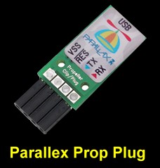
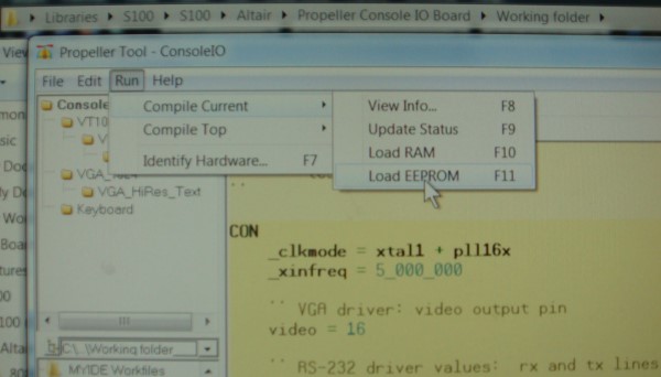
Hub RAM is the primary memory of the Propeller chip. It is entirely separate from "Cog RAM"" (See below). A program running in a Cog (whether a user program or the Propeller Spin Interpreter ) has access to the Hub RAM through the use of various word or byte instructions. The design of the Propeller is such that all of these instructions are 'atomic', which means that they will always complete in full, never partially, and if two Cogs do write to the same Hub RAM location, the value placed will be that of the last written. The value placed will never be a mix of what both Cogs attempted to write. The Hub RAM may be considered to be 32K x 8 bits, 16K x 16 bits, 8K x 32 bits or in any combination as circumstances dictate. Hub RAM is loaded from an external 32K x 8 bit I2C EEPROM after Reset or is downloaded into it from a PC based Propeller Tool (or other third-party) Propeller Boot loader. Once the Hub RAM has been loaded, a "Spin Interpreter" is loaded into Cog 0 which begins execution of the Spin program which has just been loaded. The external EEPROM and any downloaded program must always contain a Spin program to be executed, even if this is just a small Spin program to place the Propeller in an operating mode other than as a Spin interpreter. |
 |
|
 |
 |
 |
 |
This page was last modified on 09/18/2011